
Page 45 - UNITRO Alarm Annunciators
P. 45
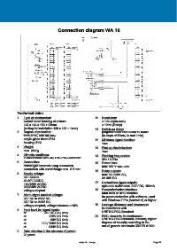
Connection diagram WA 16


            Technical data:
            1.   Type of construction:                           10.  Resolution:
                 control board housing aluminum                      ≥ 1ms (opto-mos)
                 144 x 144 x 160 + 25mm                              ≥ 10ms (Relay)
                 (cutting for installation 138 x 138 + 1mm)      11.  Switch-on delay:
            2.   Degree of protection:                               programmable from 50ms to 10min
                 front: IP50, with full-view                         (in steps of 50ms, 2s and 1min)
                 acrylic glass doors IP54                        12.  Minimum signal duration:
                 housing: IP20                                       1ms
            3.   Weight:                                         13.  First-up discrimination:
                 max. 2000g                                          1ms
            4.   Climatic conditions:                            14.  Flashing frequencies:
                 in accordance with UNITRO-PSC-Standard              2Hz / 0.5Hz
            5.   Connection:                                     15.  Power loss:
                 screw-type terminals/ plug connection               max. 6W + 16x 0.5W
                 connection with screw flange max. 2.5 mm²       16.  Relay outputs:
            6.   Supply voltage:                                     max. 5A 250V AC,
                 24V AC/DC                                           3A 30V DC
                 48-60V AC/DC                                    17.  Contactless signal outputs:
                 110/125V AC/DC
                 220/240V AC/DC                                      opto-mos switch max. 300V DC, 100mA
                 voltage-adapted                                 18.  Parameterization interface:
            7.   Alarm signal nominal voltage:                       Mini USB or NFC interface
                                                                     for parameterization with software, used
                 24V AC to 230V AC
                 24V DC to 240V DC                                   with Windows 7 Pro (Android 6) or higher
                 voltage-adapted, voltage tolerance ±10%         19.  Leakage distances and clearances:
            8.   Input level for signal inputs:                      in accordance with
                                                                     UNITRO-PSC-Standard
                 at           24V AC / DC 8mA
                 at               230V AC 7mA                    20.  EMC, immunity to interference:
                 at                60V DC 4mA                        UNITRO-PSC-Standard, immunity higher
                 at          110 / 125V DC 3mA                       degrees of severity according to the
                 at               240V DC 2mA                        actual generic standards DIN EN 61000
            9.   Data retention in the absence of power:
                 20 years

                                                      subject to change                                 Page 54