Page 31 - UNITRO Alarm Annunciators
P. 31

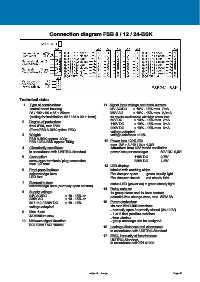
Connection diagram FSB 8 / 12 / 24-BSK


            Technical data:
              1.  Type of construction:                       11. Signal input voltage and rated current:
                  control board housing                           24V AC/DC     ± 10% - 15% max. 7mA
                  96 / 192 x 96 x 85 + 25mm                       230V AC       ± 10% - 15% max. 2,9mA
                  (cutting for installation: 92 / 186 x 92 + 1mm)   for special applications with high power loss:
                                                                  60V DC        ± 10% - 15% max. 7mA
              2.   Degree of protection:
                  front IP50, rear IP20                           110V DC       ± 10% - 15% max. 6mA
                  (Front FSB 8-BSK option IP54)                   220V DC       ± 10% - 15% max. 6mA
                                                                  voltage-adapted
              3.   Weight:                                        voltage tolerance ±10%
                  FSB 8-BSK approx. 400g
                  FSB 12/24-BSK approx. 650g                   12. Power loss 100% ED:
                                                                  max. 2W + 8 / 12 / 24 x 1,3W
              4.   Climatically conditions:                       Attention: from 60V forced ventilation
                  in accordance with UNITRO-Standard              power loss per message:       60V DC  0,5W
              5.   Connection:                                                  110V DC         0,7W
                  screw-type terminals/ plug connection                         220V DC         1,3W
                  max. 2,5 mm²                                 13. LED display:
              6.   Front panel buttons:                           labeled with marking strips
                  acknowledge horn                                Fire damper open:    green steady light
                  LED test                                        Fire damper closed:   red steady light

              7.   External button:                               status LED (power on) = green steady light
                  acknowledge horn (normally open contact)
                                                              14.  Relay outputs:
              8.   Supply voltage:                                1x group alarm and 1x horn contact,
                  24V AC/DC            ± 10 - 15% or              potential-free change-over, max. 250V 5A
                  230V AC              ± 10 - 15% or
                  60 / 110 / 220V DC   ± 10 - 15%             15.  Parameterization:
                  voltage-adapted                                 via rear Mini USB interface
                                                                  - normally open / normally closed (24-110V)
              9.   Max. fuse:                                     - 1 or 2 final position switches
                  4A medium slow                                  - time window
             10.  Minimum signal duration:                        - group message can be assigned
                  DC: 10ms / AC: 100ms                        16.  Leakage distances and clearances:
                                                                  in accordance with UNITRO-Standard
                                                              17.  EMC, immunity of interference:
                                                                  UNITRO-Standard,
                                                                  in accordance with EN 61000


                                                      subject to change                                 Page 40
   26   27   28   29   30   31   32   33   34   35   36