
Page 35 - LON-bus components
P. 35
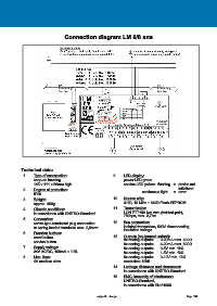
Connection diagram LM 0/8 ana
Technical data:
1. Type of construction: 9. LED-display:
snap-on housing power LED green
145 x 111 x 50mm high service LED yellow: flashing = device not
2. Degree of protection: initialized
IP20 continuous light = error
3. Weight: 10. Neuron chip:
approx. 300g 3150, 10 MHz + 64kB Flash-EEPROM
4. Climatic conditions: 11. Transmission:
in accordance with UNITRO-Standard LON FTT10A two wire (twisted-pair),
78kbps, max. 2,7km
5. Connection:
screw-type terminals/ plug connection 12. Bus connection:
or spring-loaded terminals max. 2,5mm² isolated transceiver, 500V disconnecting
insulation voltage
6. Function buttons:
reset button 13. Outputs (equipment variant):
service button 8x analog outputs: 0-20mA max. 600Ω
8x analog outputs: 4-20mA max. 600Ω
7. Supply voltage: 8x analog outputs: 0-5V min. 1kΩ
24V AC/DC, 100mA ± 10% 8x analog outputs: 1-5V min. 1kΩ
8. Max. fuse: 8x analog outputs: 0-10V min. 1kΩ
4A medium slow resolution: 12bit
14. Leakage distances and clearances:
in accordance with UNITRO-Standard
15. EMC, immunity of interference:
UNITRO-Standard,
in accordance with EN 61000
subject to change Page 134