
Page 77 - UNITRO Alarm Annunciators
P. 77
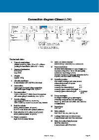
Connection diagram C3text (LON)


            Technical data:
              1.  Type of construction:                       11.  Rear LED status display:
                  control panel bay 288 x 72 x 127 + 25mm         Status of e.g. LON-bus, DCF-status etc.
                  (cutting for installation 283 x 62 + 1mm)
                                                              12.  Parameterization:
              2.  Degree of protection:                           via Mini USB-interface or LNS-PlugIn a.o.:
                  front: IP54                                     response delay (from 1s to 18h (sec grid))
                  bay: IP20                                       quiescent / operating current,
                                                                  relevant / irrelevant, message allocation to the
              3.  Weight:                                         outputs, text input and self-binding
                  approx. 750g
                                                              13.  Operating modes:
              4.  Climatic conditions:                            new value message with horn control
                  in accordance with UNITRO-Standard
                                                                  acknowledgement of reports
              5.  Connection:                                     message comes                 = +
                  screw-type terminals/ plug connection           message is acknowledged       = Q
                  with screw-type flange max. 2,5mm²              message goes unacknowledged  = -
                                                                  message goes acknowledged     = message
              6.  Bus connection:                                                                  goes
                  2 wire LON-bus FT-5000 Smart transceiver
                  with screw plug-in terminals, max. 2,7km    14.  Group messages:
                                                                  64 output contact (group messages)
              7.  Supply voltage:                                 arbitrarily assigned the 320 messages
                  24V AC/DC (=14-28V AC, 19-36V DC),              issue e.g. about 4x LM 0/16R, via LON-bus
                  230V AC/DC (= 85-265V AC, 85-250V DC), 100mA
                                                                  or C3modem
              8.  Real time clock:                            15.  Power loss:
                  battery backup (max. 10 years)                  max. 6W
                  DCF77 radio clock with optional antenna
                                                              16.  Relay outputs:
              9.  Data retention in the absence of power:         max. 250V AC, 5A, 25V DC, 5A
                  battery backup (max. 10 years)
                                                              17.  Leakage distances and clearances:
              10. Printer connector:                              in accordance with UNITRO-Standard
                  9-pin Sub-D socket RS232
                                                              18.  EMC, immunity of interference:
                                                                  UNITRO-Standard,
                                                                  in accordance with EN 61000


                                                      subject to change                                 Page 86