
Page 37 - UNITRO Alarm Annunciators
P. 37
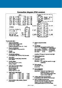
Connection diagram (PSC-version)


            Technical data:

              1.  Type of construction:                         10. Minimum signal duration:
                  control board housing plastic                    1ms
                  96 x 96 x 120 + 25mm
                  (cutting for installation: 92 x 92 + 1mm)     11. LED display:
                                                                   labeled with exchangeable marking strips
              2.  Degree of protection:                                        1 flash frequency:  2 flash frequency:
                  front IP50 (option IP54), rear IP20              alarm new alert:    red flashing   red fast flashing
                                                                   alarm acknowledge: red steady light  red steady light
              3.  Weight:                                          alarm removed:    LED off   red slow flashing
                  approx. 450g                                     alarm Reset:      LED off   LED off

              4.  Climatically conditions:                         operating-LED (power) = green steady light
                  in accordance with UNITRO-PSC-Standard
                                                                12. Flashing frequencies:
              5.  Connection:                                      2Hz / 0,5Hz
                  screw-type terminals/ plug connection         13. Power loss 100% ED:
                  max. 2,5mm²
                                                                   max. 2W + 1,5W
              6.  Supply voltage:                                  attention:  from 110V take care for enough
                  24V AC/DC to 230V AC/DC                                      ventilation!
                  voltage-adapted
                                                                14. Relay outputs:
              7.  Alarm signal nominal voltage:                    max. 5A 250V AC,
                  24V AC to 230V AC                                3A 30V DC
                  24V DC to 220V DC                             15. Parameterization:
                  voltage-adapted                                  with front buttons
                  voltage tolerance ±15%
                                                                   separately:  quiescent / operating current
              8.  Input level for signal inputs:                               switch-on delay max. 10 min
                    24V AC/DC      ± 10% - 15%      1,7mA                      ONE / TWO flashing frequencies
                    60V DC         ± 10% - 15%       2mA                       output contact assigment
                  110V DC          ± 10% - 15%      1,4mA       16. Leakage distances and clearances:
                  220V DC          ± 10% - 15%      1,1mA          in accordance with UNITRO-PSC-Standard
                  230V AC          ± 10% - 15%      1,2mA
                                                                17. EMC, immunity of interference:
              9.  Data retention in the absence of power:          UNITRO-PSC-Standard, immunity higher
                  in EEPROM
                                                                   degrees of severity according to the
                                                                   actual generic standards DIN EN 61000
                                                      subject to change                                 Page 46