
Page 17 - Optical_and_acoustic_Snap-on_alarm_modules
P. 17
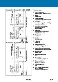
Connection diagram QC 6/BM, QC 6/B                      Technical data:
                                  8
                                 7
                                9
                           max. 10 Bausteine / modules 13
                             12
                                                                     1.  Type of construction:
                                                                        snap-on housing 100 x 75 x 130mm
                                        32
                        Brücke 11/12 an Folgebausteinen entfernen Remove strap 11/12 to downstream modules  13  12  11  10  9  8  7  S1  +  -  ~  6  5  4  3  31  30  29  28  27  26  25  24  23  22  21  Betriebssign.  operating  signals  2.  Weight:
                                                                        approx. 600g
                                                                     3.  Climatic conditions:
                                                                        in accordance with UNITRO-Standard


                                                                        overhead screw-type terminals/ plug
                                  3  6  5  4  2  1  20  19  18  17  16  Störsignale  alarms  Sammelmeldekontakt im Betriebszustan geöffnet.  4.  Connection:
                                  2     15                              connection max. 2.5mm²
                       U2         1  QC 6/B  14         Operating, group alarm open.
                          2A           N-                            5.  Alarm signal nominal voltage:
                                        33                              24V AC/DC to 230V AC
                                        32                              voltage-adapted
                                        31
                                   S1  U1  30  Betriebssign.  operating  signals
                                        29
                                  14                                 6.  Input level:
                                        28
                                  13
                                        27
                                     6
                                  12                                    at 24V AC/DC and 220V AC/DC
                                        26
                                  11  5  25
                       Blinken  quitt./  flash  ack.  Test  10  9  24   per Input approx. 8mA
                                  8  4  23
                       Hupe  quitt./  horn  ack.  7  6  3  22  21  Störsignale  alarms  7.  Contact load:
                                        20
                                     2  19                              max. 1A
                       Sammel-  meldung  group  alarm  Hupe  4  3  1  18
                                  5
                               horn
                                  2     17  16                       8.  Max. fuse:
                       U2         1  U2  QC 6/BM  15
                              max. 250V, 3A  Meldesignal-  spannung /  alarm signal  voltage U1
                          2A                     2A    Lampenspannung / lamp voltage  max. 230V, 1A  2A medium slow
                                                 L  N  N  L          9.  Power loss:
                                                                        approx. 7W
             Connection diagram QC 8/M, QC 8
                            13  12    9    7    8  31                10. Mechanical service life:
                                                                              6
                                                                        10x 10  switching operations
                        Brücke 11/12 an Folgebausteinen entfernen Remove strap 11/12 to downstream modules  max. 10 Bausteine / modules  A  R  13  12  11  10  9  8  S1  +  -  St  Out ~ In  Test  Busleitungen  Bus-line  extern  8  7  6  5  4  U1  8  7  6  5  4  30  29  28  27  26  25  24  23  22  Störsignale  alarms  11. Leakage distances and clearances:
                                                                        in accordance with UNITRO-Standard
                                                                     12. Response delay:
                                                                        approx. 15ms
                                                                        25ms
                                  4  7  6  5  3  2  3  2  21  20  19  18  17  Sammelmeldekontakt im Betriebszustan geöffnet.  13. Minimum signal duration:
                                     1
                                       1
                                  3     16
                                  2  power supply  15
                                    Netz/               Operating, group alarm open.   14. Recovery time:
                                  1    N-  14
                          2A                                            ≥ 5s / QC-8/M and QC-6/B-M
                                                                     15. First value distinction:
                                        31 8
                                  N S2  A S1  U1  30                    approx. 5ms / QC-8/M
                                     8
                                        29
                                       7
                                        28
                                  E  R
                                     7
                                        27                           16. Flashing frequencies:
                                  13  St  6  26
                                  12  11  Out ~ In  Busleitungen  Bus line  6  5  25  2Hz
                       Blinken  quitt./  flash  ack.  Test  10  9  -  +  5  24  23  Störsignale
                                  8  Test  extern  4  4  22  alarms  17. EMC, immunity of interference:
                       Hupe  quitt./  horn  ack.  7  6  3  3  21  20    UNITRO-Standard,
                                        19 2
                       Sammel-  meldung  group  alarm  Hupe  4  3  1  1  18  17  in accordance with EN 61000
                                     2
                                  5
                               horn
                                  2     16  15
                       U2         1  Netz/  power supply  14
                              max. 250V, 3A  Meldesignal-  spannung /  alarm signal  voltage U1  L  N  N  L  Lampenspannung /
                          2A           N-        2A     lamp voltage  max. 230V, 1A
                                                      subject to change                                Page 192