Page 11 - Optical_and_acoustic_Snap-on_alarm_modules
P. 11

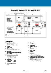
Connection diagram SVE-S16 and SVE-S24 E


                                  Netzanschluss L/N  230V AC  oder/or +/- 24V DC
              L (+)    max. 230V, 4A mtr.  power supply
              N (-)

                                           Eingänge      LP HQ   Anschluss Hupen-   Eingänge
                                           Inputs 1-8            quittierung an N (-)  Inputs 1-12
                Anschluss der Lampenprüftaste
                (Schließer) an L (+)                             horn acknowledge
                                                                 connection to N (-)
                Anschluss der Hupenquittiertaste
                (Öffner) an N (-).
                Connect lamp-test-button
                (closed contact) to L (+)
                Connect horn-acknowledge-button
                (open contact) to N (-).
                                         1     2     3     4      5     6     7     8     9     10   11    12   13  SVE    1     2     3     4      5     6     7     8     9    10    11    12     13   14  SVE
                                           Eingänge/Inputs  ST       LP    HQ      N-     L+  Eingänge/Inputs      N-   ST
                                             1-8              Netz  S16               1-12         Netz  S24E
                                                              power supply                       power supply
                                           STÖRMELDESYSTEME  extern                STÖRMELDESYSTEME
                                          Eingänge/Inputs                          Eingänge/Inputs  LP
                                             9-16                                    13-24
                                                       S1
                Busleitungen zu Erweiterungs-    14   15   16   17    18   19   20   21    DC AC     22   23   24    25   26   27    15   16   17   18    19   20   21   22   23   24   25   26     27   28
                bausteinen räumlich getrennt
                von geschalteten Energie-
                leitungen verlegen.
                S1 = AC/DC Umschaltung für
                        Meldungsspannung
                        (Batteriegleichspannung=DC)  Eingänge                       Eingänge
                                          Inputs 9-16                               Inputs 13-24
                Bus line to slave modules and               Sammel- Hupe
                                                            meldung horn
                high energy cables must be                   group
                separately mounted.                          alarm
                S1 = AC/DC switch for alarming
                        voltage (Battery voltage = DC)
              L (+)    max. 230V, 4A mtr.
              N (-)


            Technical data:

             1.  Type of construction:                             8.  Power loss:
                 snap-on housing                                      max. 7W
                 100 x 75 x 55 / 62,5mm high
                                                                   9.  Contact load:
             2.  Weight:                                              max. 5A, 250V AC
                 approx. 220g
                                                                   10. Max. fuse:
             3.  Climatic conditions:                                 4A medium slow
                 in accordance with UNITRO-Standard
                                                                   11. Signal lamps:
             4.  Connection:                                          max. 5W
                 screw-type terminals/ plug connection
                 max. 1,5mm²                                       12. Lamps-test:
                                                                      at AC: halve wave
             5.  Alarm signal nominal voltage:                        with reverse polarity voltage
                 24V AC/DC or 230V AC                              13. Leakage distances and clearances:
                 voltage-adapted
                 voltage tolerance ±15%                               in accordance with UNITRO-Standard
                                                                   14. EMC, immunity of interference:
             6.  Input level:
                 at 24V AC/DC     4mA                                 UNITRO-Standard,
                                                                      in accordance with EN 61000
                 at 230V AC     1,7mA
             7.  Minimum signal duration:
                 25ms


                                                      subject to change                                Page 186
   6   7   8   9   10   11   12   13   14   15   16